AMIGO Torso
| Part Links |
| Author |
| TU/e |
| CST Group, TU/e |
| rop@tue.nl |
| CAD Files |
| Inventor |
| STEP |
| Electrical Drawings |
| License |
| License Files |
AMIGO: Head | Arms | Torso | Base
Contents |
Part Summary
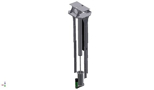
The torso contains a spindle and and a mounting space for the head, arms and some electronics.
- Author: CST Group, TU/e
- License: CERN OHL v.1.1
- Repository: https://gitlab.tue.nl/tech-united-eindhoven/rop/-/tree/master/AMIGO/Torso
- Software: http://www.ros.org/wiki/Robots/AMIGO
Overview
The shoulders are connected to the base platform via a spindle that allows the upper part of the body to move up and down. In its lowest position, AMIGO is capable to lift objects from the ground. While in its highest position the robot is about as high as a kid, making it big enough to place objects on the table or in the sink but still small enough to make a friendly appearance.
Specifications
Construction
- Dimensions (HxWxD): 85-120 x 28 x 25 cm
- Weight: +/- 20 kg
Communication
- Analog
Audio
Out
1x JBL GTO328
- Power: 75 W max
Software
- Ubuntu
- ROS (Robot Operating System)
- Programming: C++
Degrees of Freedom
Lifting mechanism
- 1 DOF
Motor Specifications
Lifting mechanism
- Maxon RE35 24 V
- Maxon Planetary gearhead GP 32A 4.8:1
- Maxon Encoder: HEDS 5540
- Maxon Brake AB 28, 24 VDC
Mechatronics
Assembly Upper Body
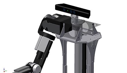
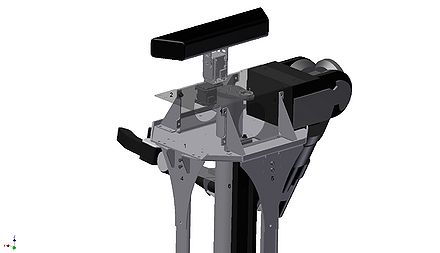
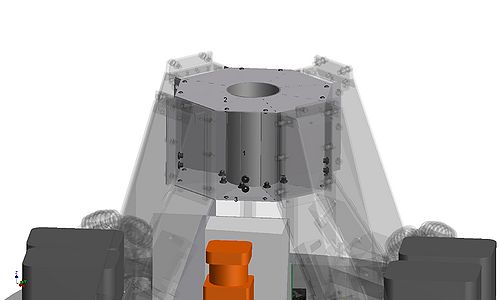
Figure 2 and 3 shows the upper body of Amigo. The upper body consists of a three millimeter aluminum base plate (1). It has an octagonal shape and six of its edges are folded to increase the out of plane bending stiffness of the plate. The flanges are welded together at the points were they meet. A U-profile (2) (made transparent to give a better view) is bolted to the base plate. The profile is folded from a two millimeter thick aluminum plate. The cross section of the profile is fixed by four triangular sheets (3) of 2 millimeter thick aluminum, which are bolted to both the u profile and the bottom plate.
The U-profile is not welded to the bottom plate, so it can still easily be disassembled to access the electronic components that are located inside the box.
The connectors of the slider rails (4) and (5) differ in size. Connector (4) is bolted to the shoulder, which is placed at the end of the u profile. (See Figure 4). Connector (5) is wider than (4). It has the same width as the flaps of the u profile. Therefore, its outer edges are directly beneath the triangular sheets. This prevents unnecessary moments in the base plate. The connectors are also made of aluminum.
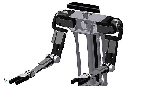
Figure 5 shows the upper body with the arms attached. The arms close the box. This creates a stiff connection between them. Each arm is bolted to the upper body frame with 8 M5 bolts. These are the mounting points that are already available at the arms.
Support of the Upper Body
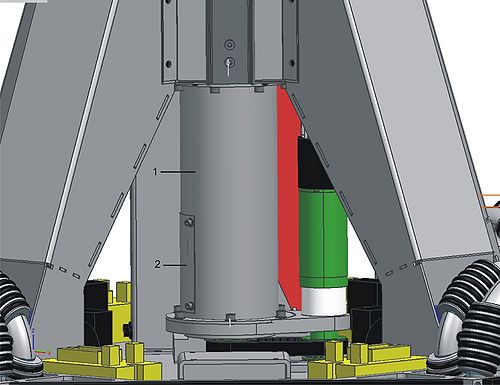
The axial forces on the upper body are supported by the aluminum tube. Forces in all other directions and applied moments are supported by the slider rails. The aluminum tube is guided by a tube (1) (See Figure 5) between the two floors in the octagonal cone (2) and (3). The tube is made of aluminum. It has flanges at both ends. These are used to bolt it to the two floors and center the tube in these floors. The cone is made out of two halves. This allows both easy manufacturing and easy access to the components inside the cone. The halves are folded from a two millimeter thick aluminum plate. The inner diameter of the guidance tube is one millimeter larger than the outer diameter of the aluminum tube. This clearance prevents over determination of the upper body, because it is also guided by the four slider rails. It is important that the slider rails are mounted exactly vertical. Therefore, there must be some room for adjustments in the connection between the slider rails and the upper body. For this reason, the diameter of the bolt holes in the connectors of the slider rails ((4) in Figure 2 and 3) is two millimeter larger than the diameter of the bolt. Therefore, the position of the connector can be adjusted with respect to the upper body. The connector (5) has rivnuts to provide the threaded holes. To create the adjustment space the diameter of the holes in the bottom plate ((1) in Figure 2 and 3) is two millimeter larger than the bolt diameter.
The flexible cable chain (6) (in figures 2 and 3) guides the cables during translation of the upper body. One end of the guidance is connected to the upper body and the other end is connected to the back half of the cone. Holes are made in the two floors to allow the guidance to pass through them.
Lifting Mechanism
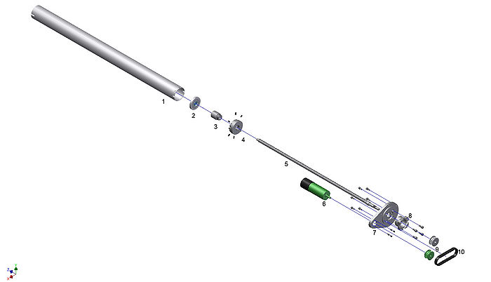
AMIGO’s upper body is lifted by a ball screw spindle mechanism. An exploded view of this mechanism is depicted in Figure 6. One end of the spindle (5) is supported by an axial support (8) and the other end by a deep groove roller bearing (2). A teflon ring is placed around the bearing to reduce the friction between the bearing and the tube it slides through.
The outer shape of the nut (3) is adjusted by screwing it in an extra connector (4). The tube is connected to this connector with 6 M4 set screws. The connector is a milled aluminum part. The tube is a standard aluminum tube from MCB with and outer diameter of 50 mm and a wall thickness of 1.5 mm.
The axial support is bolted to the motor spindle support (7) with 4 M4 bolts. This support is a milled aluminum part. Also the motor assembly (7) is bolted to this support with 4 M3 counter sunk bolts. The power from the motor is transferred to the spindle via a tooth belt drive train (9) (10).
The mechanism has a stroke of 435 mm.
Connection of the Lifting Mechanism to the Rest of the Frame
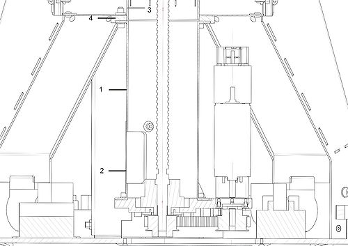
Figure 7 shows the connection between the lifting mechanism and the rest of the frame. The connection is made by an aluminum tube (1) with two flanges. The tube is a standard MCB part. It has an outer diameter of 70 mm and a wall thickness of 1.5 mm. The flanges are 2 mm thick and are welded to the tube. A hole is made in the tube to access the components inside. The hole is covered by a cover plate (2) that is bolted to the tube. Figure 3 shows a cross section view of the connection. The tube (1) and cover (2) can be recognized in this Figure. Figure 4 shows that the tube is centered on the motor_spindle_support and on the tube of the central box (3). To center the connecting tube on the tube of the central box an extra body (4) is used, which is also made out of aluminum. The tube (3) is four millimeter longer than the height of the central box. The extra body (4) is centered on this extra part of the tube. The flange of the connecting tube (1) is centered on the extra body. The connecting tube and the tube of the central box do not touch each other. This ensures a good alignment of the spindle with respect to the central box. Both parts are bolted to the central box with 8 M4 bolts.
License
Copyright Technische Universiteit Eindhoven 2011.
This documentation describes Open Hardware and is licensed under the CERN OHL v. 1.1.
You may redistribute and modify this documentation under the terms of the CERN OHL v.1.1. (http://ohwr.org/cernohl).
This documentation is distributed WITHOUT ANY EXPRESS OR IMPLIED WARRANTY, INCLUDING OF MERCHANTABILITY, SATISFACTORY QUALITY AND FITNESS FOR A PARTICULAR PURPOSE. Please see the CERN OHL v.1.1 for applicable conditions.


